电线电缆允许电流计算公式
The maximum continuous current that flows in an insulated wire is called allowable current. This value is calculated from the permissible rise in temperature during continuous use, ambient temperature, and wiring conditions as follows:
a) Allowable current in Junkosha Fluoropolymer Wires is given by:
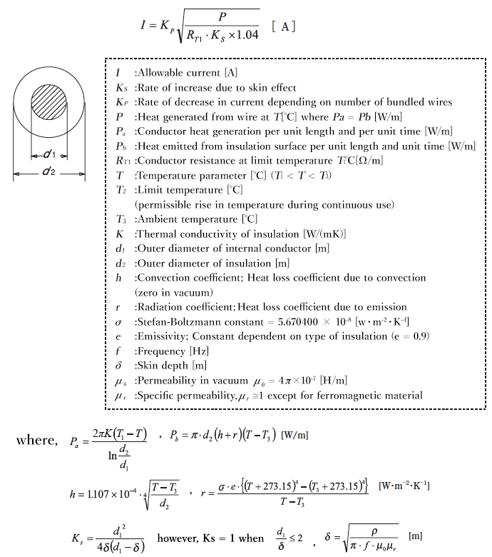
b) How to calculate allowable current of wires & cables
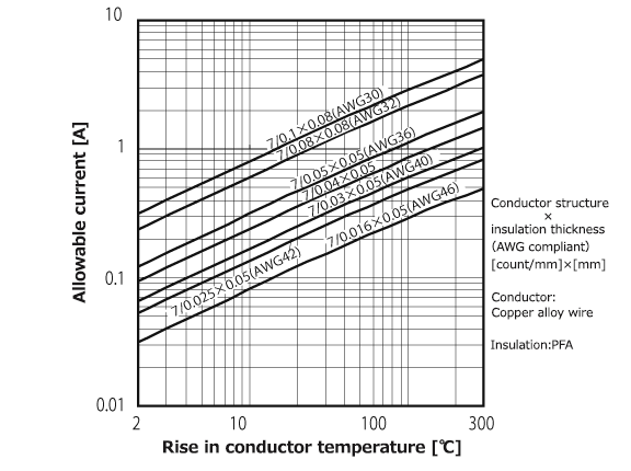
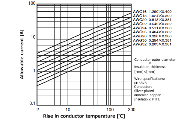
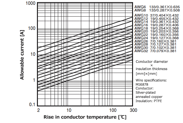
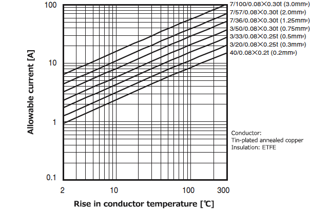
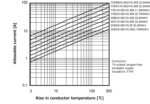
First, based on the previous calculation, estimate temperature Τ[℃] meeting Ρa = Ρb, and then calculate allowable current I using P at this estimated temperature. The graphs (1-2-1~1-2-8) in the next section show I values calculated for typical wires and cables. The notation “at atmospheric pressure” means that temperature rises when wire is laid horizontally in the air at 20℃ with no airflow (no wind).
-
Determine the “rise in conductor temperature” (ΔΤ) based on ambient temperature, upper-limit temperature rise due to other adjacent components, or maximum continuous operating temperature for the insulation or conductor. Typically, the rated temperature of the wire is taken as the upper-limit temperature.
Table 1-2-1 Maximum continuous operating temperature for wire material 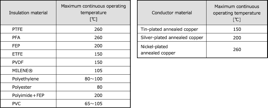
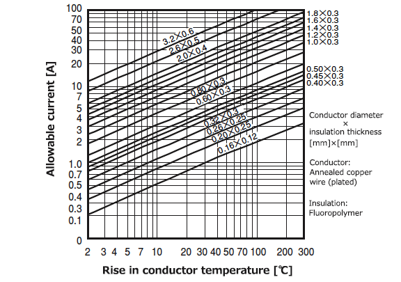
- Read current [A] directly off of the graph by erecting a perpendicular to the x-axis at a given point of ΔΤ (rise in conductor temperature provided in ①) until it hits the conductor outer diameter line or wire type line.
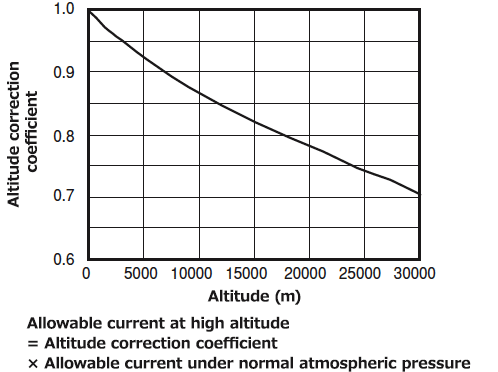
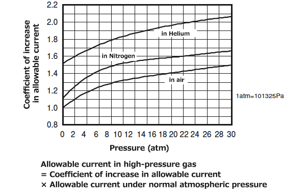
- Allowable current in a vacuum is about 1/2 to 1/3 that under atmospheric pressure. Figure 1-2-2 shows examples of calculation. For use in high-pressure gas and under low pressure at high altitudes, multiply the correction coefficients shown in Figures 1-2-9 and 1-2-10, respectively, by the value for atmospheric pressure.
- For use in the form of a bundle of many wires or cables, or in a parallel configuration, multiply the correction coefficient for the bundle.
- For use at high frequency (400Hz or higher), multiply the correction coefficient for AC resistance √(1/Ks) by the current value read in the figure.
- For such conductors as copper alloy wires for which conductivity constants are not 100%IACS, multiply the correction coefficient for conductivity (%IACS) √(Conductivity/100) by the current read in the figure.
- Increases as the conductor cross-sectional area becomes larger;
- Increases as pressure rises, and decreases as pressure falls; when in a vacuum, it is about 1/2 to 1/3 the value under normal atmospheric pressure;
- Increases in Junkosha Fluoropolymer Wires which have a larger ΔΤ; In other words, it is possible to make the cross-sectional area of them smaller when the same allowable current is desirable; and
- Little depends on the type or thickness of insulation when ΔΤ is the same; the current read from the conductor outer diameter or cross-sectional area can be used as is even when the insulation thickness is somewhat different.
c) Allowable Current Calculation
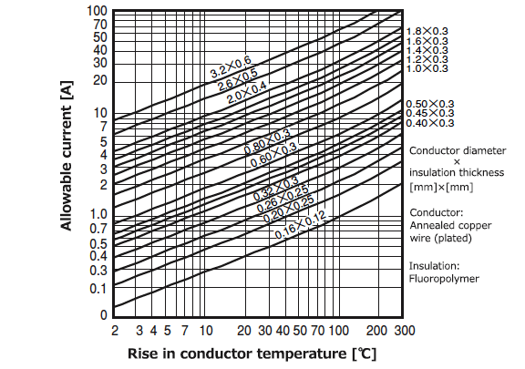
appliance wiring under normal atmospheric pressure
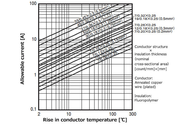
under normal atmospheric pressure
under normal atmospheric pressure
(measured by Junkosha)
[based on SAE - AS50881 (formerly MIL-W-5088L)]